The energy system of the residential demonstrator in Oud-Heverlee is equipped with different types of hot-water vessels used for thermal energy storage. These storage units offer, combined with the solar collectors, the possibility to increase the production and the self-consumption of locally produced renewable energy. It is evident that mismatches between generation by solar collectors and thermal energy demand exist on different time scales. On one hand, the production peak on a daily basis occurs around noon, while Domestic Hot Water (DHW) and Space Heating (SH) demand is mostly needed in the morning and the evening. Short-term storage is therefore needed to bridge this gap. On a yearly scale on the other hand, solar production has the highest potential during the summer, when space heating demands are low or non-existing. Seasonal storage can provide a solution to store excess heat produced in the summer to be used for heating purposes in winter time.
At this demonstrator, the energy system of the residential building was equipped with a 400L solar boiler to provide DHW and two identical 12 m3 underground seasonal storage tanks. All storage systems can exchange heat with the main solar collector circuit. The use of sensible heat, the cheapest and most convenient option, for long-term thermal energy storage is subject to thermal losses to the surroundings which might hamper its applicability.
The extensively monitored energy system in this H2020 STORY project provides an ideal opportunity to monitor these storage units and to develop state-of-charge (SOC) methods to estimate their energy content during operation. This knowledge is of high importance to efficiently control the system.
In this blog update we report on the recent developments and findings related to these storage units.
How seasonal is long-term storage?
The seasonal storage tanks are used in multiple scenario’s including charging of the different DHW tanks (both indoor and outdoor) and charging the indoor heating storage tank, used for space heating purposes. In each case, there is a choice between using only the heat from the seasonal storage or using the heat from the solar collectors prior to discharging the seasonal tanks.
In any of the scenarios described above, it is necessary that temperature of the extracted heat in the seasonal storage tanks exceeds the required temperatures for the desired applications. In case of space heating this is usually 40 to 45 °C, while it is a bit higher for DHW production: 45 to 55 °C, depending on the user’s needs.
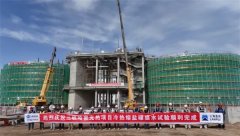
During the 2017-2018 cycle, the seasonal storage tanks were charged during summer and left idle during the heating season to assess losses and the impact on the storage efficiency. A selected example is shown in Figure 1 below, showing the end of the charging cycle with a maximum average tank temperature of 63 °C reached mid-July.
The average temperature[1] in the tank decreases steadily and drops below 40 °C before November 2017. Direct use of the tanks is therefore not possible during most of the winter season. The energy remaining in the tank could still be used as a low-temperature heat source for the indoor heat pump, as an alternative to the shallow geothermal source. This alternative use case is not foreseen at the moment.
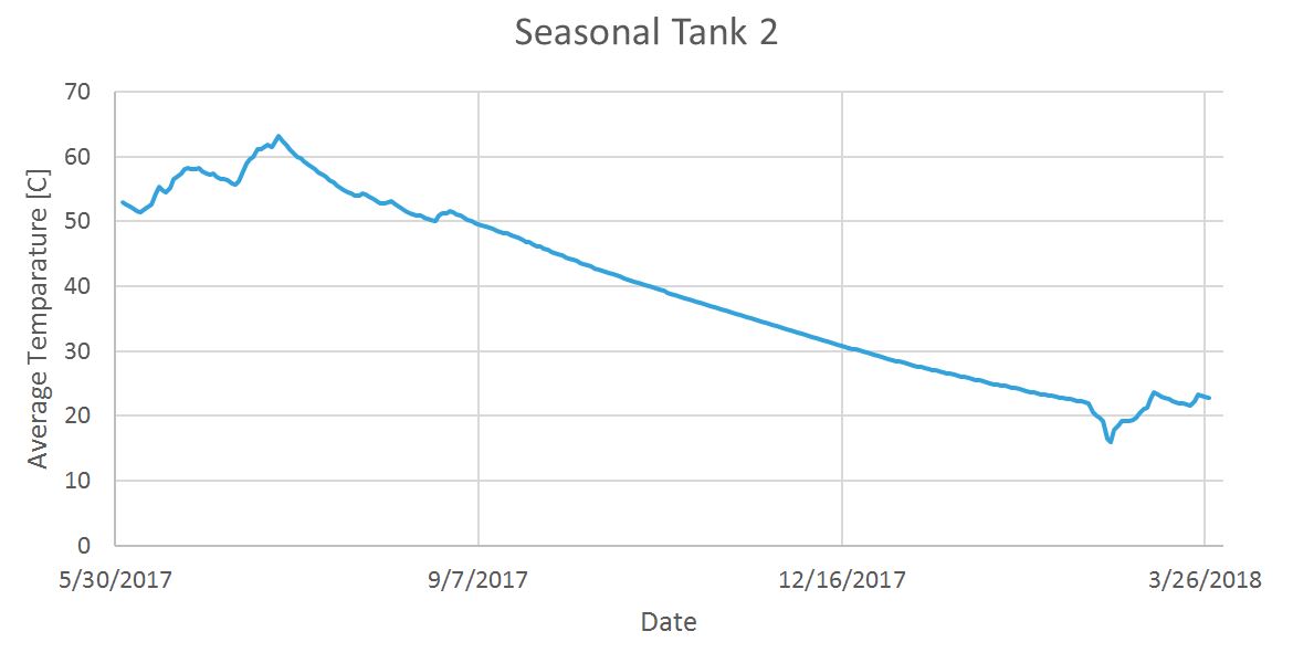
Figure 1: daily average tank temperature between June 1st 2017 and March 31st2018
Some considerations should be added to the conclusion above since it was the first time this underground seasonal storage system was operated. Losses can be expected to play a less pronounced role after temperature stabilization of the underground. Also, the temperature of the system at the end of the charging cycle will play a role in the determining how long the storage system can be used effectively. To have a better overview on that, Figure 2 shows the estimated average temperature of the seasonal storage as a function of idling time for different initial conditions.
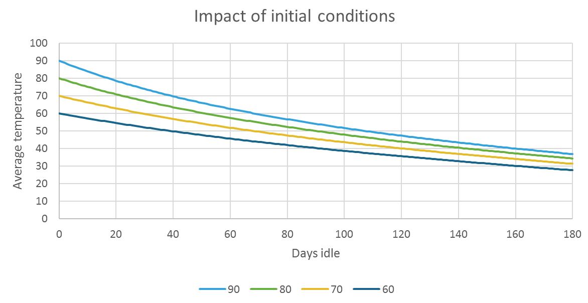
Figure 2: Estimated average temperature decay of the seasonal storage system in idle mode, for different initial conditions
Figure 3 is an alternative representation of Figure 2 , displaying the number of days the average tank temperature is above a given minimum (different colors) provided a set of initial conditions. The tanks can indeed be used for a longer period for direct heating if the maximum charging temperature can be increased. Discharge of the tank will decrease the average tank temperature with 0.07 °C per kWh extracted.
Figure 3: Number of days that the average storage temperature is above a given minimum temperature when idle. Different initial conditions are separated on the x-axis and each bar represents a set minimum temperature.
What about short term storage?
The 400-litre solar boiler is in a technical room and equipped with an internal heat exchanger (1.5 m2 surface) that is used to load the tank, using the solar collectors or the seasonal storage tanks. A custom-made temperature measuring device containing 7 equally-spaced point sensors is installed to monitor the temperature at different heights within the tank. To develop and validate the SOC determination method, a series of tests, shown in Figure 4, has been performed on the tank: charging, discharging, idling and simultaneous charge and discharge.
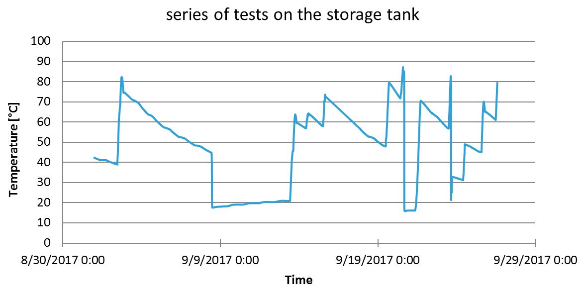
Figure 4: temperature in the middle of the DHW tank during a series of charging, idling and discharging tests.
Looking further in detail, Figure 5 shows the loading and idling cycle during which the tank was charged to a temperature of 83 °C and left to cool down. The tank’s surrounding temperature is also monitored and plotted at the secondary y-axis. It can be noticed that after having the tank charged homogeneously, the cooling down happens at different rates and the stratification of the tank is clearly visible.
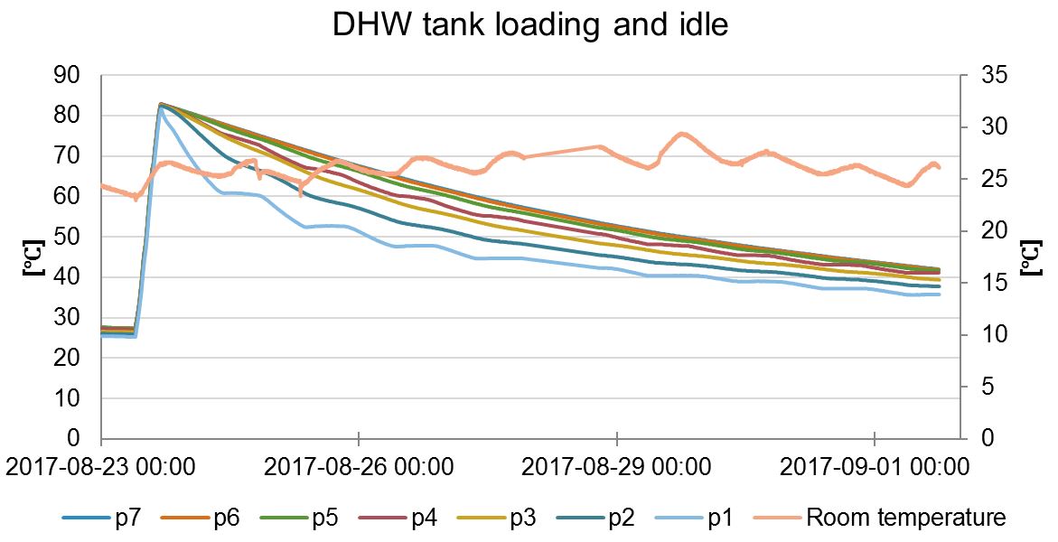
Figure 5: Loading and idling of the DHW storage tank. Sensors p1-p7 show the temperature of the water at different heights, from top to bottom respectively (left y-axis) and the room temperature is shown on the right y-axis.
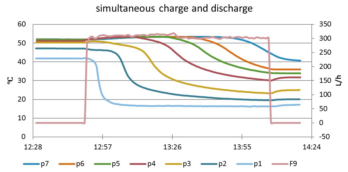
Figure 6: Loading and idling of the DHW storage tank. Sensors p1-p7 show the temperature of the water at different heights, from top to bottom respectively (left y-axis) and the discharge flow, F9 is shown on the right y-axis.
Moreover, Figure 6 show the case where the storage tank is being discharged and charged at the same time, at a lower rate. It can be noticed that the top layer discharge very quickly and the other layers follow. Due to the existence of the heat exchanger at the bottom of the tank, the lower layers are emptied at a lower rate than the top layer, as is clear from the figure.(By Jan Diriken & Jad Al Koussa)
[1] The maximum difference between two sensors does not exceed 2 °C during the idle period